PORTABLE WIRELESS CHARGING STAND
ME 37100: Computer-Aided Design
Spring 2022
Objective
This project aims to design a portable wireless charging stand capable of carrying the loads from a typical phone and tablet. This charging stand allows individuals to charge their devices on the go and use it to view their devices hands-free. It is angle adjustable to allow consumers to view their device at the desired angle. FEA is conducted along with a collision test and cost analysis to test the viability of the design.
Design Conceptualization
Based on the intended purpose of the stand, the design I came up with is shown in the figure below. There are two variations of the designs with two different hinge mechanisms. The first hinge mechanism will have two cylindrical bodies on opposing ends of the front plate with a protruding pin that will insert into the middle cylindrical body on the base plate. The second pin mechanism will have three hollow cylindrical bodies, which will be locked into each other using a hinge pin. The standing leg will fit into the base plate slots to help adjust the stand's angle. When the stand has folded, the leg of the stand will fold into the base plate. The benefit of this design is that it is compact, the battery is built into the structure, and the leg folds into the base plate.

Design conceptualization of the phone stand
CAD Model
The stand was designed on SolidWorks based on the requirements and the specifications set forth during the initial design stage of this project. Dimensions of the stand were formulated using known dimensions of a standard phone, tablet, and portable battery, which are currently on the market. The portable wireless charging stand was split into five major components:
-
Base plate
-
Device holder
-
Front center plate
-
Backplate (leg of stand)
-
Pin for the hinge
Since the device has rotating components collision detection test was conducted using SolidWorks to determine whether the components of the stand can rotate without interfering with each other. Based on the test, adjustments to the stand dimensions and design were made accordingly.


SolidWorks CAD Files
Schematic of the final assembly of stand and the components. The slideshow also includes results of the collision detection test.
Finite Element Analysis

Convergence Study:

Convergence study
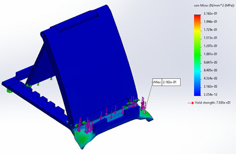
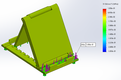
Stress Analysis for Assembly with an applied load on the hinge:


VonMises Stress distribution when a 50 N force is applied to the top of the hinge
SY stress distribution when a 50 N force is applied to the top of the hinge

URES displacement distribution when a 50 N force is applied to the top of the hinge
Stress Analysis on the front plate:


Maximum stress produced on the face plate when a load of 8N was applied.

Maximum displacement on the face plate with an applied load of 8N.


VonMises Stress distribution when a 50 N force is applied on the front plate
SY stress distribution when a 50 N force is applied on the front plate

URES displacement distribution when a 50 N force is applied on the front plate
Stress Analysis on the base plate:

VonMises Stress distribution when a 50 N force is applied on the top of the base plate
SY stress distribution when a 50 N force is applied on the base plate

URES displacement distribution when a 50 N force is applied on the base plate
Stress Analysis on the back plate:

VonMises Stress distribution when a 8N force is applied on the back plate

VonMises Stress distribution when a 50 N force is applied on the back plate
Cost Analysis

Result / Outcome
This project was successful in creating a simple and useful design of portable wireless charging stands. The functionality of the design was tested through simulation and collision detection test. Stress analysis of the top piece and hinge confirmed that our stand is efficient under ideal load. Such a redesign demonstrates more functions to the user by minimizing space due to its easy-to-carry size and portable battery bank.